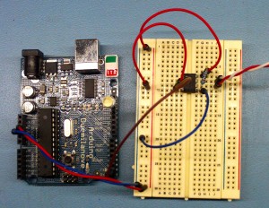
Nothing fancy here, just trying to get started with RS485 and Arduino. So here we go for a basic setup with one master that only emits and one slave that just listens. See the comments for the wiring:
/* RS 485 V1 Master, using a SN75176BP

                              -------
                          RO -|     |- VCC [connect to 5v]
                              |     |
                          RE -|     |- B-------------->   [connect to Slave's B]
                              |     |        | 120R (parallel resistor)
          connect to 5V   DE -|     |- A-------------->   [connect to Slave's A]
                              |     |
   connect to pin 1 (TX)  DI -|     |- GND [connect to GND]
                              -------

*/
const int ledPin = 13;      // the pin that the LED is attached to

void setup() {
  Serial.begin(9600);
  pinMode(ledPin, OUTPUT);
}

void loop() {

  byte b = 0;

  Serial.write(b);
  analogWrite(ledPin, b);
  delay(1000);

  b=255;

  Serial.write(b);
  analogWrite(ledPin, b);
  delay(1000);
}
And now for the slave:
/* RS 485 V1 SLAVE, using a SN75176BP

                              -------
   connect to pin 0 (RX)  RO -|     |- VCC [connect to 5v]
                              |     |
          connect toGND   RE -|     |- B-------------->   [connect to Master's B]
                              |     |        | 120R (parallel resistor)
                          DE -|     |- A-------------->   [connect to Master's A]
                              |     |
                          DI -|     |- GND [connect to GND]
                              -------

YOU'LL HAVE TO DISCONNECT RO DURING UPLOAD TO I/O BOARD!!!!!!!!!

*/
const int ledPin = 13;      // the pin that the LED is attached to

void setup() {
  Serial.begin(9600);
  pinMode(ledPin, OUTPUT);
}

void loop() {
  byte brightness;

  if (Serial.available()) {// check if data has been sent from the computer:

    brightness = Serial.read(); // read the most recent byte (which will be from 0 to 255):

    analogWrite(ledPin, brightness); // set the brightness of the LED:
  }
}
If all goes according to the plan, you should see something like this:
